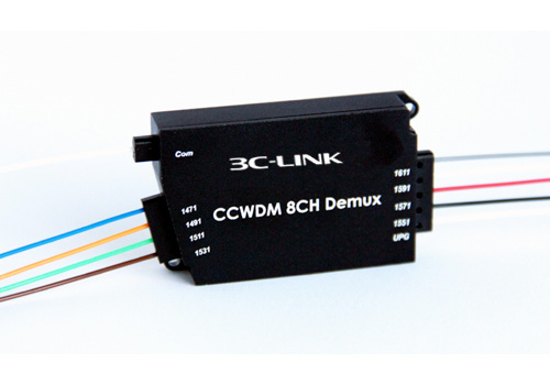
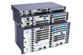
CCWDM Module


Network operators face a persistent challenge to support increasing data traffic while maintaining capital and operational expenditures. Technology advances are needed to sustain this model across product generations. Sometimes these advances come in the form of a new technology, such as Dense Wavelength Division Multiplexing (DWDM) or coherent detection in optical networking. In other cases, these advances take the form of incremental improvements that may leverage Moore’s law, integrated photonics, and higher bandwidth component technology. Sometimes, these advances enable network operators to make architectural changes with benefits greater than the sum of the individual improvements.
Over the last 10 years, advances in optical transport based on digital coherent detection have enabled significant improvements in the cost per bit by transmitting higher capacity. To achieve this higher capacity, vendors have increased the bandwidth of components, utilized higher order modulations, and improved algorithms, such as Forward Error Correction (FEC). At the same time, advances in CMOS process nodes and integrated photonics have enabled smaller pluggable form factors and lower power dissipation.
As coherent interfaces have evolved from bulky discrete solutions toward pluggable, there has generally been a “density penalty” associated with transport optics compared to the client optics that are used in data centers. Some solutions have attempted to overcome this by offering higher data rates in larger form factors, but this still requires customized hardware for transport applications. Network operators have long wanted transport optics at the same data rates and in the same form factors as client optics, as was possible at 10G using SFP+ form factor.
Supporting transport optics in the same form factors as client optics is beneficial for network operators because it allows simpler architectures that reduce cost. Combined with the recent industry trend toward open line systems, these transport optics can be plugged directly into a router, eliminating the need for an external transmission system. This can simplify the control plane, while reducing cost, power, and footprint.
As some hyperscale network operators began planning for 400G architectures, they saw an opportunity to address this challenge for Data Center Interconnections (DCIs) with reaches less than 120km. The Optical Internetworking Forum (OIF) started a project in 2016 to standardize interoperable coherent interfaces with power budgets that could support the form factors, such as QSFP-DD and OSFP, that were expected to be deployed for 400G client optics. With these form factors in mind, OIF focused on a specific application in which performance could be sacrificed in the interest of meeting a 15W module power target.
OIF demonstrated that interoperable standards for coherent were possible, and the 400ZR solution gained momentum in the industry. In parallel, system vendors demonstrated that improved thermal performance could be achieved in these high-density form factors, which allowed DSP and module vendors to support additional functionality and higher performance. Building on the success of OIF, other standards bodies, such as Open ROADM, had defined standards for applications beyond DCI that included additional features and higher performance. Open ROADM is designed for OTN-based networks that require support for additional protocols that can increase the ratio of overhead bits.
By targeting Ethernet-based transport, OpenZR+ can offer increased functionality and performance with reduced complexity, power, and implementation penalty. Leveraging elements of both OIF and Open ROADM, OpenZR+ allows network operators to achieve these benefits without sacrificing interoperability between modules. This white paper will discuss some specific use cases that can benefit from OpenZR+ operation.
oFEC is a critical element of OpenZR+ MSA compliant Digital Coherent Optics. The oFEC engine is a block-based encoder and iterative Soft-Decision (SD) decoder. With 3 SD iterations the Net Coding Gain is 11.1dB @ BER 10-15 (DP-QPSK) and 11.6dB @ BER 10-15 (DP-16QAM), with pre-FEC BER threshold of 2×10⁻². The combined latency of the encoder and decoder is less than 3µs. The higher gain FEC allows OpenZR+ modules to achieve greater reaches and overcome link impairments, such as narrow filtering or dispersion effects, while low latency is beneficial in a variety of access and data center applications.
Key benefits of the 400G OpenZR+ MSA specification relative to 400ZR are:
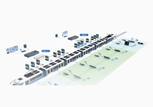
4x 100GE multiplexing on OpenZR+ transceivers is valuable in operator networks in which all routers have not yet been migrated to 400GE. The 4x 100GE mode allows for 400GE-ready and 100GE-capable routers to talk to each other. An example of such a layout is shown below. A 4x100GE muxponder that hosts an 400G OpenZR+ transceiver can break 400G OpenZR+ interface on a router to 4x 100GE QSFP28 clients to connect into 100GE ports on the far-end router.
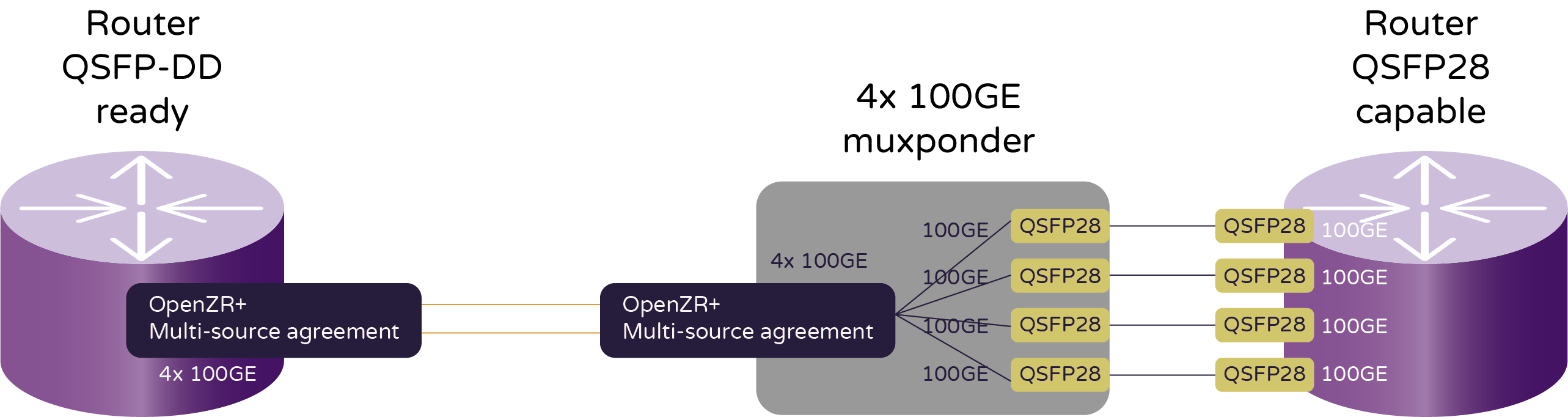
Figure 1. 4x 100GE break-out use case for 400G OpenZR+
As coherent technology has progressed to enable 400G DWDM in the form factor of a QSFP-DD transceiver, a key set of questions we need to ask are the following:
To understand the line system design implications, we should understand the coherent OpenZR+ transmitter and receiver constraints that we are operating under.
The key transmitter specifications for OpenZR+ that affect the add-drop on the terminal site are as follows:
The key receiver specifications for OpenZR+ that affects the add-drop on the terminal site are as follows:
The figure below summarizes a typical line system layout for 400G OpenZR+.
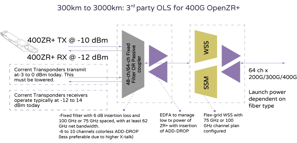
Figure 2. Add-drop and terminal layout for OpenZR+
Most line systems in long-haul applications use flex-grid ROADM (Reconfigurable Optical Add-Drop Multiplexers) for flexibility of the channel plan in Nx6.25GHz increments and hybrid EDFA + counterpropagating Raman amplifiers to maximize link OSNR.
To enable 400G OpenZR+ on such an infrastructure, we need to use an appropriate add-drop structure. A few add-drop options exist:
The objective for the operator would be to set up the terminal with Mux or AAWG with an incremental OSNR > 32dB.
In this section, we will review performance for a few different sample line systems.
The common set of assumptions are 80km G652 SMF28 spans and GN model to consider linear and nonlinear OSNR contributions. Commercial 9- or 20-port flex grid WSS, Variable gain EDFAs, and 1W counterpropagating Raman amplifiers are considered in this design. The amplifiers also have embedded midstage DGEs to manage gain ripple from the Raman amplification.
The EDFA amplifiers operate at 5.5dB of noise figure, and the combined noise figure contribution of the EDFA + Raman amplifier for a link is 0.6dB.
The transponder receiver performance figures are characterized in the OpenZR+ MSA specification, and key aspects to consider are as follows:
The penalty contributions can be lumped into an OSNR penalty budget of 1.5 dB for EDFA-only and 2 dB for EDFA + Raman.
Let’s consider the example of Corning G.652 SMF28 fiber and EDFA amplifiers over 480km with six spans of 80km each at 0.22dB/km. The add-drop structure used is a 48-channel 100GHz AAWG.
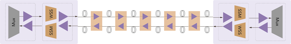
Figure 3. 6x 80km G.652 SMF28 fiber link with EDFA amplifiers only
The terminal incremental OSNR contribution that includes the transmitter in-band OSNR, add-drop X-talk, add-drop EDFA ASE noise, terminal WSS filtering and booster EDFA noise is designed to provide at least 32 dB of OSNR.
For each link,

Note:
A worst-case (aging, temperature, frequency, large sample size, receive power of -12dBm) back-to-back OSNR threshold of 24dB and transmission impairment penalty of 1.5dB leaves 0.44dB of margin.
Let’s consider the example of Corning G.652 SMF28 fiber and Raman + EDFA-based amplifiers over 1040km with 13 spans of 80km each at 0.22dB/km. The add-drop structure used is a 48-channel 100GHz AAWG.
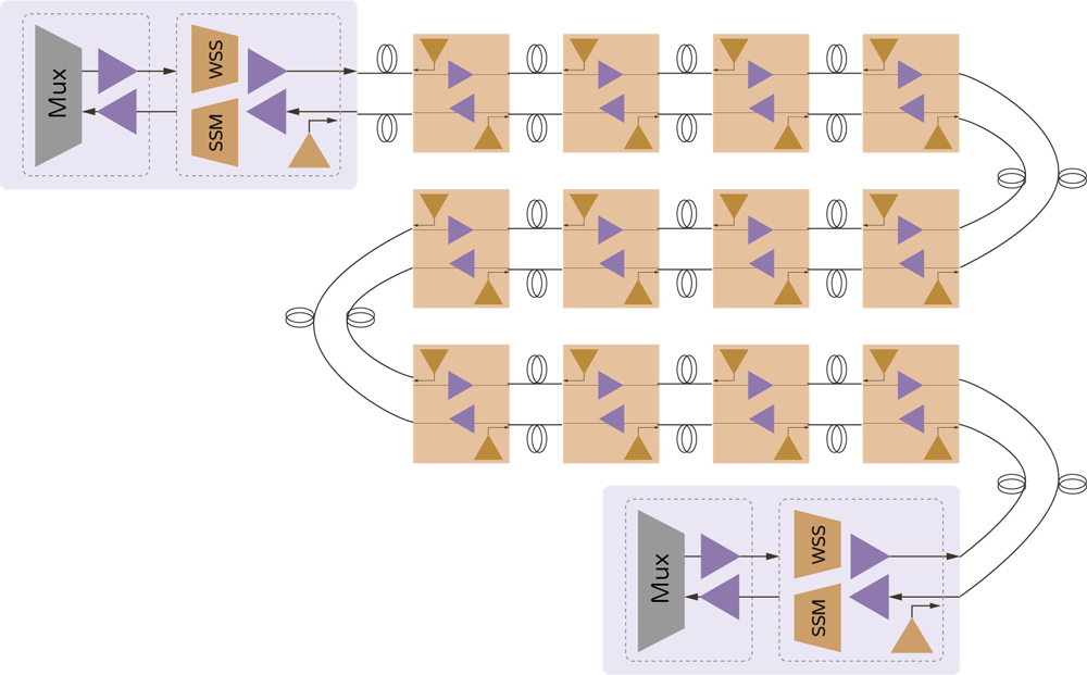
Figure 4. 13x 80km G.652 SMF28 fiber link with EDFA + Raman amplifiers
The terminal incremental OSNR contribution that includes the transmitter in-band OSNR, add-drop X-talk and add-drop EDFA ASE noise and terminal WSS filtering and booster EDFA noise is designed to provide at least 32dB of OSNR.
A worst-case (aging, temperature, frequency, sample, mix receive power of -12dBm) back-to-back OSNR threshold of 24dB and transmission impairment penalty of 2dB leaves 0.04dB of margin.
Below is a summary of performance results over SMF28 fiber for the various OpenZR+ modes.
| OpenZR+ modes | EDFA-only (km) | EDFA and Raman amplifier (km) |
|---|---|---|
| 400ZR+ (ZR400-OFEC-16QAM) | 480 | 1040 |
| 300ZR+ (ZR300-OFEC-8QAM) | 1600 | 2320 |
| 200ZR+ (ZR200-OFEC-QPSK) | 2880 | 2880 |
| 100ZR+ (ZR100-OFEC-QPSK) | 5840 | 5840 |
OpenZR+ MSA provides a digital coherent optic transceiver that can be plugged into a range of routing, switching, or optical transport host platforms. With 400G, 300G, 200G, and 100G modes, long-haul applications can also be addressed. The 4x100GE multiplexing mode allows for the connecting of 400GE- and 100GE-capable devices across a DWDM link.

Copyright © 2022 3c-link Corporation Limited.VOKO提供网站技术支持
Privacy Policy